
Activity Diagram
This content is for v7. Switch to the latest version for up-to-date documentation.
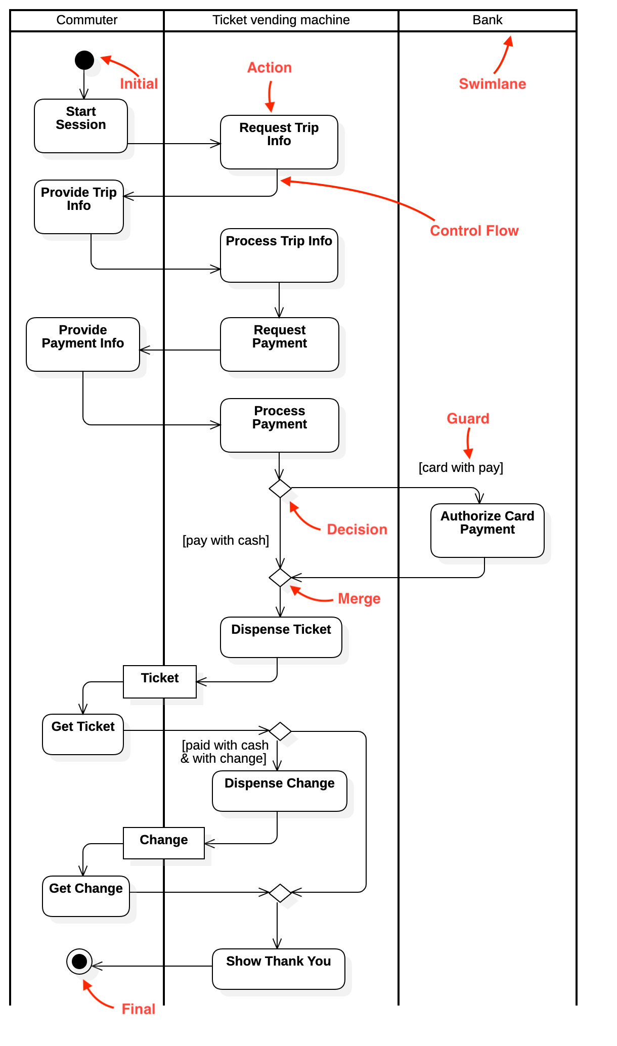
Create Activity Diagram
Section titled “Create Activity Diagram”To create an Activity Diagram:
- Select first an element where a new Activity Diagram to be contained as a child.
- Select Model | Add Diagram | Activity Diagram in Menu Bar or select Add Diagram | Activity Diagram in Context Menu.
See also
UML Activity Diagram - For more information about UML Activity Diagram.
Action
Section titled “Action”To create an Action:
- Select Action in Toolbox.
- Drag on the diagram as the size of Action.
You can use QuickEdit for Action by double-click or press Enter on a selected Action.
-
Name Expression : Edit name expression.
Syntax of Name Expression
expression ::= [ '<<' stereotype `>>` ] [ visibility ] namestereotype ::= (identifier)visibility ::= '+' | '#' | '-' | '~'name ::= (identifier) -
Add Input Pin : Add an input pin.
-
Add Output Pin : Add an output pin.
-
Add Note : Add a linked note.
-
Add Constraint : Add a constraint.
-
Add Trigger Event : Add a trigger event.
-
Add Outgoing Control Flow : Add an outgoing control flow with an action.
-
Add Incoming Control Flow : Add an incoming control flow with an action.
-
Add Outgoing Object Flow : Add an outgoing object flow with an object node.
-
Add Incoming Object Flow : Add an incoming object flow with an object node.
-
Add Decision : Add a decision with two additional actions.
-
Add Merge : Add a merge with two additional actions.
-
Add Fork : Add a fork with two additional actions.
-
Add Join : Add a join with two additional actions.
-
Add Initial Node : Add an initial node with a connected control flow.
-
Add Final Node : Add an final node with a connected control flow.
Trigger
Section titled “Trigger”To add a Trigger:
- Select an Action.
- Select Model | Add | Trigger in Menu Bar or Add | Trigger in Context Menu.
Initial Node
Section titled “Initial Node”To create an Initial Node:
- Select Initial in Toolbox.
- Click at the position on the diagram.
Activity Final Node
Section titled “Activity Final Node”To create an Activity Final Node:
- Select Activity Final in Toolbox.
- Click at the position on the diagram.
Fork Node
Section titled “Fork Node”To create a Fork Node:
- Select Fork in Toolbox.
- Drag on the diagram as the size of Fork.
Join Node
Section titled “Join Node”To create a Join Node:
- Select Join in Toolbox.
- Drag on the diagram as the size of Join.
Merge Node
Section titled “Merge Node”To create a Merge Node:
- Select Merge in Toolbox.
- Click at the position on the diagram.
Decision Node
Section titled “Decision Node”To create a Decision Node:
- Select Decision in Toolbox.
- Click at the position on the diagram.
Swimlane (Partition)
Section titled “Swimlane (Partition)”To create a Swimlane (Vertical or Horizontal):
- Select Swimlane (Vertical) or Swimlane (Horizontal) in Toolbox.
- Drag on the diagram as the size of Swimlane.
You can use QuickEdit for Model Element (See Model Element).
Interruptible Activity Region
Section titled “Interruptible Activity Region”To create an Interruptible Activity Region:
- Select Interruptible Activity Region in Toolbox.
- Drag on the diagram as the size of Interruptible Activity Region.
Structured Activity Node
Section titled “Structured Activity Node”To create a Structured Activity Node:
- Select Structured Activity in Toolbox.
- Drag on the diagram as the size of Structured Activity Node.
You can use QuickEdit for Model Element (See Model Element).
Input Pin
Section titled “Input Pin”To create an Input Pin:
- Select Input Pin in Toolbox.
- Click on an Action where Input Pin to be attached.
Output Pin
Section titled “Output Pin”To create an Output Pin:
- Select Output Pin in Toolbox.
- Click on an Action where Output Pin to be attached.
Send Signal
Section titled “Send Signal”To create a Send Signal:
- Select Send Signal in Toolbox.
- Drag on the diagram as the size of Send Signal.
Send Signal is actually an Action whose kind is sendSignal.
Accept Signal
Section titled “Accept Signal”To create an Accept Signal:
- Select Accept Signal in Toolbox.
- Drag on the diagram as the size of Accept Signal.
Accept Signal is actually an Action whose kind is acceptSignal.
Accept Time Event
Section titled “Accept Time Event”To create an Accept Time Event:
- Select Accept Time Event in Toolbox.
- Drag on the diagram as the size of Accept Time Event.
Accept Time Event is actually an Action whose kind is timeEvent.
Flow Final Node
Section titled “Flow Final Node”To create a Flow Final Node:
- Select Flow Final in Toolbox.
- Click at the position on the diagram.
Object Node
Section titled “Object Node”To create a Object Node:
- Select Object Node in Toolbox.
- Drag on the diagram as the size of Object Node.
You can use QuickEdit for Object Node by double-click or press Enter on a selected Object Node.
-
Name Expression : Edit name expression.
Syntax of Name Expression
expression ::= [ '<<' stereotype `>>` ] [ visibility ] namestereotype ::= (identifier)visibility ::= '+' | '#' | '-' | '~'name ::= (identifier) -
Visibility : Change visibility property.
-
Add Note : Add a linked note.
-
Add Constraint : Add a constraint.
-
Add Outgoing Object Flow : Add an outgoing object flow with an object node.
-
Add Incoming Object Flow : Add an incoming object flow with an object node.
-
Add Outgoing Control Flow : Add an outgoing control flow with an action.
-
Add Incoming Control Flow : Add an incoming control flow with an action.
Central Buffer
Section titled “Central Buffer”To create a Central Buffer:
- Select Central Buffer in Toolbox.
- Drag on the diagram as the size of Central Buffer.
You can use QuickEdit for Object Node (See Object Node).
Datastore
Section titled “Datastore”To create a Datastore:
- Select Datastore in Toolbox.
- Drag on the diagram as the size of Datastore.
You can use QuickEdit for Object Node (See Object Node).
Activity Parameter Node
Section titled “Activity Parameter Node”To create an Activity Parameter Node:
- Select Activity Parameter Node in Toolbox.
- Drag on the diagram as the size of Activity Parameter Node.
If you set the name as blank, the associated parameter’s textual notation will be shown as the name.
You can use QuickEdit for Object Node (See Object Node).
Expansion Region
Section titled “Expansion Region”To create a Expansion Region:
- Select Expansion Region in Toolbox.
- Drag on the diagram as the size of Expansion Region.
You can use QuickEdit for Model Element (See Model Element).
Input Expansion Node
Section titled “Input Expansion Node”To create an Input Expansion Node:
- Select Input Expansion Node in Toolbox.
- Click on an Expansion Node where Input Expansion Node to be attached.
Output Expansion Node
Section titled “Output Expansion Node”To create an Output Expansion Node:
- Select Output Expansion Node in Toolbox.
- Click on an Expansion Node where Output Expansion Node to be attached.
Control Flow
Section titled “Control Flow”To create a Control Flow:
- Select Control Flow in Toolbox.
- Drag from a node and drop on another node.
You can use QuickEdit for Relationship (See Relationship).
Object Flow
Section titled “Object Flow”To create an Object Flow:
- Select Object Flow in Toolbox.
- Drag from a node and drop on another node.
Exception Handler
Section titled “Exception Handler”To create an Extension Handler:
- Select Extension Handler in Toolbox.
- Drag from a node and drop on another node.
Activity Interrupt
Section titled “Activity Interrupt”To create an Activity Interrupt:
- Select Activity Interrupt in Toolbox.
- Drag from a node and drop on another node.
You can use QuickEdit for Relationship (See Relationship).