StarUML documentation
v7
v7
  • Introduction
  • User Guide
    • Introduction
    • Basic Concepts
    • Managing Project
    • Managing Diagrams
    • Diagram Editor
    • Editing Elements
    • Formatting Elements
    • Annotation Elements
    • Managing Extensions
    • User Interface
    • CLI (Command Line Interface)
    • Validation Rules
    • Keyboard Shortcuts
    • TouchBar (MacBook)
    • Customization
  • Mermaid Support
  • Working with UML Diagrams
    • Class Diagram
    • Package Diagram
    • Composite Structure Diagram
    • Object Diagram
    • Component Diagram
    • Deployment Diagram
    • Use Case Diagram
    • Sequence Diagram
    • Communication Diagram
    • Timing Diagram
    • Interaction Overview Diagram
    • Statechart Diagram
    • Activity Diagram
    • Information Flow Diagram
    • Profile Diagram
  • Working with SysML Diagrams
    • Requirement Diagram
    • Block Definition Diagram
    • Internal Block Diagram
    • Parametric Diagram
  • Working with Additional Diagrams
    • Entity-Relationship Diagram
    • Flowchart Diagram
    • Data Flow Diagram
    • C4 Diagram
    • BPMN Diagram
    • Mindmap Diagram
    • Wireframe Diagram
    • AWS Architecture Diagram
    • GCP Architecture Diagram
  • Developing Extensions
    • Getting Started
    • Commands
    • Menus
    • Keymaps
    • Toolbox
    • Accessing Elements
    • Creating, Deleting and Modifying Elements
    • Working with Selections
    • Defining Preferences
    • Using Dialogs
    • Registering to Extension Registry
Powered by GitBook
On this page
  • Create Deployment Diagram
  • Node
  • Deployment
  • Communication Path
  1. Working with UML Diagrams

Deployment Diagram

PreviousComponent DiagramNextUse Case Diagram

Create Deployment Diagram

To create a Deployment Diagram:

  1. Select first an element where a new Deployment Diagram to be contained as a child.

  2. Select Model | Add Diagram | Deployment Diagram in Menu Bar or select Add Diagram | Deployment Diagram in Context Menu.

See also

Node

To create a Node:

  1. Select Node in Toolbox.

  2. Drag on the diagram as the size of Node.

To create a Node (model element only) by Menu:

  1. Select an Element where a new Node to be contained.

  2. Select Model | Add | Node in Menu Bar or Add | Node in Context Menu.

You can use QuickEdit for Node by double-click or press Enter on a selected Node.

  • Name Expression : Edit name expression.

    Syntax of Name Expression

    expression ::= [ '<<' stereotype `>>` ] [ visibility ] name
    stereotype ::= (identifier)
    visibility ::= '+' | '#' | '-' | '~'
    name ::= (identifier)
  • Visibility : Change visibility property.

  • Add Note : Add a linked note.

  • Add Constraint : Add a constraint.

  • Add Attribute (Ctrl+Enter) : Add an attribute.

  • Add Operation (Ctrl+Shift+Enter) : Add an operation.

  • Add Reception : Add a reception.

  • Add Communicating Node : Add a communicating node.

  • Add Deployed Component : Add a deployed component.

  • Add Deployed Artifact : Add a deployed artifact.

Deployment

To create an Deployment:

  1. Select Deployment in Toolbox.

  2. Drag from an element (to be deployed) and drop on a Node.

Communication Path

To create an Communication Path:

  1. Select Communication Path in Toolbox.

  2. Drag from a Node and drop on another Node.

- For more information about UML Deployment Diagram.
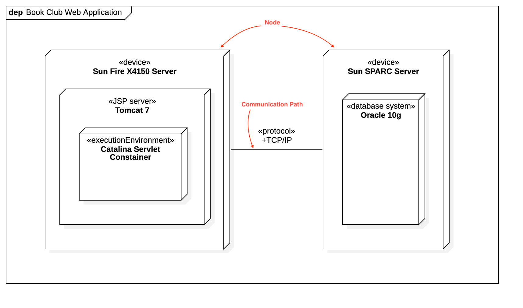
To suppress Attributes, see .

To suppress Operations, see .

To show or hide Operation Signatures, see .

You can use QuickEdit for Relationship (See ).

You can use QuickEdit for Association (See ).

UML Deployment Diagram
Suppress Attributes
Suppress Operations
Show Operation Signature
Relationship
Association
Deployment Diagram (from uml-diagrams.org)