Profile Diagram

Create Profile Diagram
To create a Profile Diagram:
Select first an element where a new Profile Diagram to be contained as a child.
Select Model | Add Diagram | Profile Diagram in Menu Bar or select Add Diagram | Profile Diagram in Context Menu.
See also
UML Profile Diagram - For more information about UML Profile Diagram.
Profile
To create a Profile (model element only) by Menu:
Select an Element where a new Profile to be contained.
Select Model | Add | Profile in Menu Bar or Add | Profile in Context Menu.
MetaClass
To create a MetaClass:
Select MetaClass in Toolbox.
Drag on the diagram as the size of MetaClass.
To create a MetaClass (model element only) by Menu:
Select an Element where a new MetaClass to be contained.
Select Model | Add | MetaClass in Menu Bar or Add | MetaClass in Context Menu.
You can use QuickEdit for MetaClass by double-click or press Enter on a selected MetaClass.
Name Expression : Edit name expression.
Syntax of Name Expression
Visibility : Change visibility property.
Add Note : Add a linked note.
Add Constraint : Add a constraint.
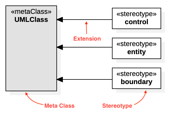
Add Stereotype : Add a stereotype with a connected extension.
Stereotype
To create a Stereotype:
Select Stereotype in Toolbox.
Drag on the diagram as the size of Stereotype.
To create a Stereotype (model element only) by Menu:
Select an Element where a new Stereotype to be contained.
Select Model | Add | Stereotype in Menu Bar or Add | Stereotype in Context Menu.
You can use QuickEdit for Stereotype by double-click or press Enter on a selected Stereotype.
Name Expression : Edit name expression.
Syntax of Name Expression
Visibility : Change visibility property.
Add Note : Add a linked note.
Add Constraint : Add a constraint.
Add Attribute (
Ctrl+Enter) : Add an attribute.Add Operation (
Ctrl+Shift+Enter) : Add an operation.Add Sub-Stereotype : Add a sub-stereotype.
Add Super-Stereotype : Add a super stereotype.
To suppress Attributes, see Suppress Attributes.
To suppress Operations, see Suppress Operations.
To show or hide Operation Signatures, see Show Operation Signature.
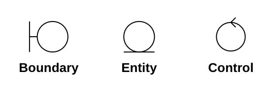
Stereotype Icon
You can assign an icon for stereotype in two ways:
Image : Select an image file (PNG, JPEG) to the
imageproperty in Property Editor.Icon Script : Write an icon script in
contentproperty in Property Editor.
Stereotype's width property and height property represents minimal width and minimal height of the icon respectively.
The assigned icon is shown when you set Format > Stereotype Display to Decoration, Decoration with Label, Icon, Icon with Label of the view elements.
Icon Script
You can use very tiny icon script language to represent a stereotype icon as below:
The icon script must starts with !icon header. The width and height in !icon header doesn't mean the actual icon size but means XY coordinates for the drawing commands. For example, if !icon 40 40 is given, you can draw shapes in (0, 0) ~ (40, 40) coordinates.
Please note that the default line color and fill color are the view element's line color and fill color. If you use the command %l or %f without argument, the line color or the fill color is set to the view element's line color or fill color.
Here is an example of icon script for the entity, boundary, control standard stereotypes in UMLStandardProfile.

Extension
To create a Extension:
Select Extension in Toolbox.
Drag from a Stereotype and drop on a MetaClass.
You can use QuickEdit for Relationship (See Relationship).